Internal Architecture of Intel 8086 Microprocessor
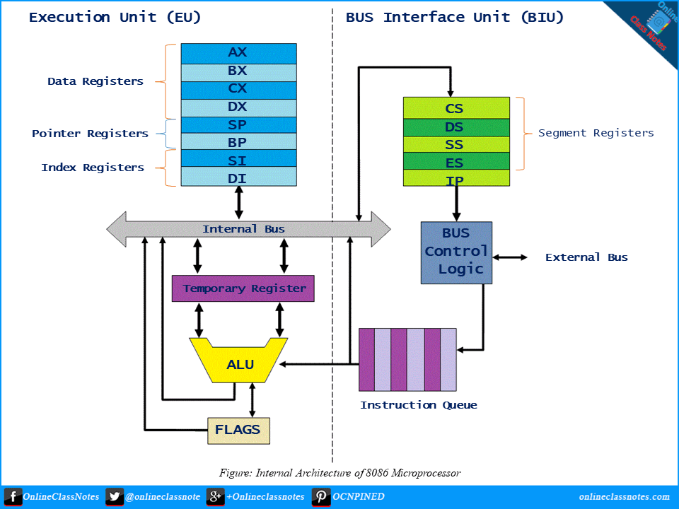
The Intel 8086, also called the iAPX 86, is a 16-bit microprocessor designed by Intel Corporation in between 1976-1978. This Intel 8086 microprocessor gave rise to the x86 architecture or 16-bit architecture. The figure given below is the internal architecture of Intel 8086 microprocessor
Features of 8086 Microprocessor:
8086 includes an Instruction Queue, which is used to store 6 instructions bytes at most at a time while an instruction is getting executed. This queuing improves the performance.
The 8086 microprocessor performs faster operations as it has registers, internal and external buses and ALU, all of 16-bit. Microprocessor 8086 can execute an instruction and fetch the following instruction simultaneously.
The 8086 microprocessor performs faster operations as it has registers, internal and external buses and ALU, all of 16-bit. Microprocessor 8086 can execute an instruction and fetch the following instruction simultaneously.
Intel 8086 microprocessor has two units; Execution Unit (EU) and Bus Interface Unit (BIU). They are dependent and get worked by each other.
Working Principles of Intel 8086 Microprocessor
Execution of instructions can be used to explain the working principles of the microprocessor. This is given below,
- The BIU outputs the contents of the instruction pointer register (IP) onto the address bus, causing the selected byte or word to be read into the BIU.
- Register IP is incremented by 1 to prepare for the next instruction fetch.
- Once inside the BIU, the instruction is passed to the queue.
- Assuming that the queue is initially empty, the EU immediately draws this instruction from the queue and begins execution.
- While the EU is executing this instruction, the BIU proceeds to fetch a new instruction. Depending on the execution time of the first instruction, the BIU may fill the queue with several new instructions before the EU is ready to draw its next instruction.
The BIU is programmed to fetch a new instruction whenever the queue has room for two additional bytes. There are three conditions that will cause the EU to enter a “wait” mode or BIU to suspend fetching.
- The first one occurs when the instruction requires access to a memory location. Here the BIU must suspend fetching instructions and output the address of this memory location. Then the EU will resume execution.
- The second will occur when the instruction to be executed is a “jump” instruction. In this case control is to be transferred to a new non-sequential address.
- The third one will occur during the execution of an instruction that is slow to execute. For example, the instruction AAM (ASCII Adjust for Multiplication) requires 83 clock cycles to complete. At four cycles per instruction fetch, the queue will be completely filled during the execution of this single instruction.
Registers of 8086 Microprocessor
In computer architecture, a processor register is a quickly accessible location available to a computer’s central processing unit (CPU). Registers usually consist of a small amount of fast storage, although some registers have specific hardware functions, and may be read-only or write-only. Registers are normally measured by the number of bits they can hold, for example, an “8-bit register”, “32-bit register” or a “64-bit register” (or even with more bits).
General Registers
General Registers or General Purpose Registers are a kind of registers which can store both data and addresses. All general registers of the Intel 8086 microprocessor can be used for arithmetic and logic operations.
AX (Accumulator)
This is accumulator register. It gets used in arithmetic, logic and data transfer instructions. In manipulation and division, one of the numbers involved must be in AX or AL
BX (Base Register)
This is base register. BX register is an address register. It usually contain a data pointer used for based, based indexed or register indirect addressing.
CX (Count Register)
This is Count Register. This serves as a loop counter. Program loop constructions are facilitated by it. Count register can also be used as a counter in string manipulation and shift/rotate instruction.
DX (Data Register)
This is data register. Data register can be used as a port number in I/O operations. It is also used in multiplication and division.
SP (Stack Pointer)
This is stack pointer register pointing to program stack. It is used in conjunction with SS for accessing the stack segment.
BP (Base Pointer)
This is base pointer register pointing to data in stack segment. Unlike SP, we can use BP to access data in the other segments.
SI (Source Index)
This is source index register which is used to point to memory locations in the data segment addressed by DS. Thus when we increment the contents of SI, we can easily access consecutive memory locations.
DI (Destination Index)
This is destination index register performs the same function as SI. There is a class of instructions called string operations that use DI to access the memory locations addressed by ES.
Segment Registers
There are four segment registers, CS (Code Segment), DS (Data Segment), ES (Extra Segment) and SS (Stack Segment).
CS (Code Segment)
Code segment (CS) is a 16-bit register containing address of 64 KB segment with processor instructions. The processor uses CS segment for all accesses to instructions referenced by instruction pointer (IP) register. CS register cannot be changed directly. The CS register is automatically updated during far jump, far call and far return instructions.
Stack segment (SS)
Stack segment is a 16-bit register containing address of 64KB segment with program stack. By default, the processor assumes that all data referenced by the stack pointer (SP) and base pointer (BP) registers is located in the stack segment. SS register can be changed directly using POP instruction.
Data segment (DS)
Data segment is a 16-bit register containing address of 64KB segment with program data. By default, the processor assumes that all data referenced by general registers (AX, BX, CX, DX) and index register (SI, DI) is located in the data segment. DS register can be changed directly using POP and LDS instructions.
Extra segment (ES)
Extra segment is a 16-bit register containing address of 64KB segment, usually with program data. By default, the processor assumes that the DI register references the ES segment in string manipulation instructions. ES register can be changed directly using POP and LES instructions.
It is possible to change default segments used by general and index registers by prefixing instructions with a CS, SS, DS or ES prefix.
IP (Instruction Pointer):
To access instructions the 8086 uses the registers CS and IP. The CS register contains the segment number of the next instruction and the IP contains the offset. IP is updated each time an instruction is executed so that it will point to the next instruction. Unlike other registers the IP can’t be directly manipulated by an instruction, that is, an instruction may not contain IP as its operand.
Flag Registers:
Intel 8086 has 16 flag registers among which 9 are active. The purpose of the flag register is to indicate the status of the processor. It does this by setting the individual bits called flags. There are two kind of flag registers; status flag register and control flag register. Status flag register reflect the result of an operation executed by the processor. The control flag registers enable or disable certain operations of the processor. The 9 active flag registers are Carry Flag (CF), Parity Flag (PF), Auxiliary Flag (AF), Zero Flag (ZF), Sign Flag (SF), Trap Flag (TF), Interrupt Flag (IF), Direction Flag (DF) and Overflow Flag (OF).
Carry Flag (CF)
This flag is set to 1 when there is an unsigned overflow. For example when you add bytes 255 + 1 (result is not in range 0…255). When there is no overflow this flag is set to 0.
Parity Flag (PF)
This flag is set to 1 when there is even number of one bits in result, and to 0 when there is odd number of one bits.
Auxiliary Flag (AF)
This is set to 1 when there is an unsigned overflow for low nibble (4 bits).
Zero Flag (ZF)
This set to 1 when result is zero. For non-zero result this flag is set to 0.
Sign Flag (SF)
This is set to 1 when result is negative. When result is positive it is set to0. (This flag takes the value of the most significant bit.)
Trap Flag (TF)
This is used for on-chip debugging.
Interrupt Enable Flag (IF)
When this flag is set to 1 CPU reacts to interrupts from external devices.
Direction Flag (DF)
This flag is used by some instructions to process data chains, when this flag is set to 0 – the processing is done forward, when this flag is set to 1the processing is done backward.
Overflow Flag (OF)
This is set to 1 when there is a signed overflow. For example, when you add bytes 100 + 50 (result is not in range -128…127).

