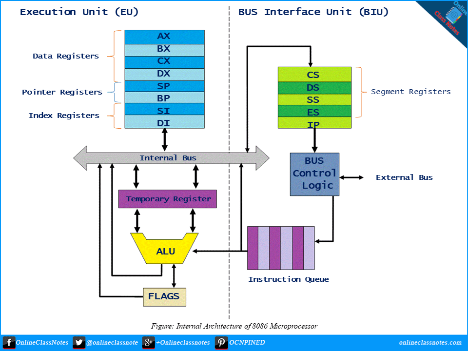
Internal architecture of 8086 microprocessor
If we study the internal architecture of 8086 microprocessor, we can see that it has two major units; Execution Unit (EU) and Bus Interface Unit (BIU). They are dependent and work with each other.
In the following given figure, which is a block diagram of 8086 microprocessor, it can be seen it is internally divided into two separate functional units. These are the Bus Interface Unit (BIU) and the Execution Unit (EU). These two functional units can work simultaneously to increase system speed and hence the throughput. Throughput is a measure of number of instructions executed per unit time.
Below is a short description of these two units.

Execution Unit (EU)
Execution unit receives program instruction codes and data from the BIU, executes them and stores the results in the general registers. It can also store the data in a memory location or send them to an I/O device by passing the data back to the BIU. This unit, EU, has no connection with the system Buses. It receives and outputs all its data through BIU.
ALU (Arithmetic and Logic Unit)
The EU unit contains a circuit board called the Arithmetic and Logic Unit. The ALU can perform arithmetic, such as; +,-,×,/ and logic such as OR, AND, NOT operations.
Registers
A register is like a memory location where the exception is that names instead of numbers denote these locations. It has 4 data registers, AX, BX, CX, DX and 2 pointer registers SP, BP and 2 index registers SI, DI and 1 temporary register and 1 status register FLAGS . AX, BX, CX and DX registers has 2 8-bit registers to access the high and low byte data registers. The high and low bytes of AX are AH and AL respectively. Similarly, the high and low bytes of BX, CX, DX are BH and BL, CH and Cl, DH and DL respectively. All the data, pointer, index and status registers are of 16 bits. Else these, the temporary register holds the operands for the ALU and the individual bits of the FLAGS register reflect the result of a computation.
Bus Interface Unit
As the execution unit (EU) has no connection with the system Busses, bus interface unit (BIU) handles this job. BIU and EU connects with each other using an internal bus. It provides a full 16-bit bi-directional data bus and 20-bit address bus. The bus interface unit is responsible for performing all external bus operations. BIU connects EU with the memory or I/O circuits. It is responsible for transmitting data, addresses and control signal on the busses.
6 Functions of Bus Interface Unit
- It sends address of the memory or I/O.
- It fetches instruction from memory.
- It reads data from port/memory.
- It Writes data into port/memory.
- It supports instruction queuing.
- It provides the address relocation facility.
To implement these functions the BIU contains the instruction queue, segment registers instruction pointer, address summer and bus control logic
Segment Registers
BIU has 4 segment busses which are CS, DS, SS, ES. These all 4 segment registers hold the addresses of instructions and data in memory. The processor uses these values to access memory locations.
It also contains 1 pointer register IP. IP contains the address of the next instruction to executed by the EU.
Instruction Queue
BIU also contain an instruction queue. When the execution unit (EU) executes instructions, the BIU gets up to 6 bytes of the next instruction and stores them in the instruction queue and this process is called instruction prefetch. This is a process to speed up the processor. Also when the EU needs to be connected with memory or peripherals, BIU suspends instruction prefetch and performs the needed operations.
